Upgrading the Timing System at HZDR ELBE
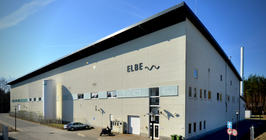
The ELBE centre for high power radiation sources is such a cutting-edge facility operated by the research laboratory HZDR (Helmholtz-Zentrum Dresden Rossendorf). ELBE utilises an electron linear accelerator to generate secondary radiation, such as positrons, neutrons, intense THz and IR pulses and Bremsstrahlung.
In the last two decades, ELBE’s engineers have successfully modified and extended the timing system to enable new experiments. On the other hand, maintenance of the timing system had become an increasingly challenging exercise, as parts of the system are using obsolete components.
A few years ago, HZDR decided to make ELBE’s timing system more homogenous by employing the Micro Research Finland (MRF) hardware platform. The latter will allow control-system engineers to adopt new and more complex trigger patterns easier.
This upgrade, which is currently in progress, will enable the parallel operation of two electron sources and future kickers to serve multiple end-stations at the same time. The selected MRF hardware enables low jitter emission of timing patterns and a long-term delay compensation of the distribution network.
Cosylab is currently in the final phase of development of the MRF-based upgrade at ELBE, in close cooperation with the HZDR engineering team, and plans to commission the system in 2022.
System hardware
The Micro Research Finland hardware allows a modular approach to the timing system with a highly flexible topology. On the one hand, event master modules (EVMs) are responsible for timing-event generation and distribution; on the other hand, event receiver modules (EVRs) set the state of physical outputs based on received events.
We decided on using the MicroTCA form factor for the system hardware wherever possible, but certain user/experiment stations will use PCIe cards. The latter allows for up to 10 trigger outputs in a smaller package and are more cost-effective.
Each of the two ELBE injectors will have an event master module, generating an independent timing pattern, allowing for autonomous operation in separate beamlines and common emission into the ELBE accelerator.
Beam diagnostics, low-level frequency control (LLRF) and other devices that need coordinated triggering will be connected to the event receiver modules in several ways. The latter will be through MicroTCA backplane trigger lines, front panel output (if TTL level is needed) or through any of the Universal Modules that provide a variety of optical and electrical level triggers.
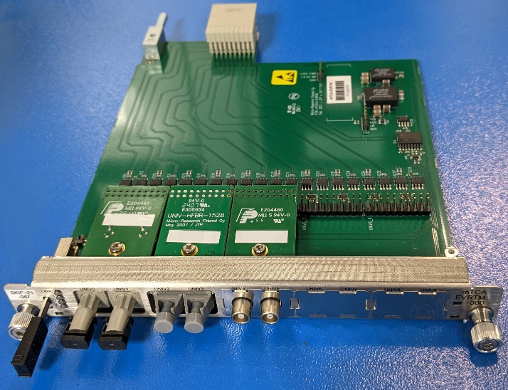
In MicroTCA EVR the number of external outputs is limited to 8 per module, four front panel TTL trigger signals and four signals from Universal Modules (two Universal Modules with two signals each). Nevertheless, Micro Research Finland extends the number of trigger signals via the rear transition module (RTM), where up to ten additional external trigger output signals (five Universal Modules) can be configured and routed.
The type of the input or output signal from the RTM is determined by the type of the Universal Input/Output (I/O) module selected, as shown in Figure 1.
All Micro Research Finland boards (EVMs and EVRs) from the 300 series provide a delay compensation feature that continuously measures event propagation delay throughout the distribution network. The event receiver modules repeatedly adjust their internal delay to match a programmed desired target delay. Each of the event receiver modules can have a different target delay setpoint. Nevertheless, adjusting the target delay on an EVR will hold you back for approximately 15 minutes while the measurement and the loopback mechanism stabilises.
Synchronising the timing system
To synchronise the new timing system with the accelerator RF, the engineering team will lock the internal oscillator of the master event master modules to an externally provided frequency of 130 MHz through the dedicated input on the master EVM’s front panel. This external reference frequency will be locked to the 1.3 GHz RF frequency and the 26 MHz thermionic gun master oscillator. It will provide a 130 MHz event clock rate to distribute the timing events from the EVMs to the EVRs.
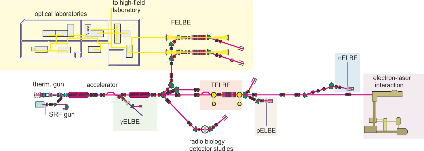
ELBE has multiple beamlines (as shown in Figure 2), but at the moment, only one kicker is used to split the beam into two beamlines. A dedicated bunch pattern will be generated and sent to the appropriate gun for each beamline branch. A combined interlock and logic block shall interleave the pulse trains and allow the machine interlock system to disable individual gun clock signals.
The engineers foresee an upgrade to the machine protection system (MPS). The system will then react to interlock events after the kicker and disable only the corresponding pulse train.
The timing system will support the parallel injection of the two-electron sources, and the Micro Research Finland timing hardware already has the capabilities to support the former.
This will allow the team to upgrade ELBE for simultaneous multi-user experiments.
To fully leverage this feature, however, injector sections of ELBE will have to be modified to be susceptible to beams at different energies.
System software
Software for the new timing hardware employs the EPICS control system framework with the support of the mrfioc2 and s7plc modules. The software allows for creating required timing event patterns based on a requested operation mode, such as continuous wave (CW), macro pulsed or single pulsed beam. Predefined operation modes simplify the operation of the timing system for the end-users and enable a high level of automated parameter settings.
Users can take advantage of two types of graphical user interfaces (GUI) to configure the timing system. While EPICS GUI is mainly for expert control and debugging, the WinCC SCADA system — which includes all ELBE machine controls — caters to the central system control.
All the machine parameters which users enter, and operation mode dependent derivatives, are checked by the verification part of the timing software and by a master programmable logic controller (PLC). The latter is the primary interface for the machine protection system.
We use a simulator written in Python to test the connection and interaction between the timing system software and master PLC during the development phase.
Pattern Generation
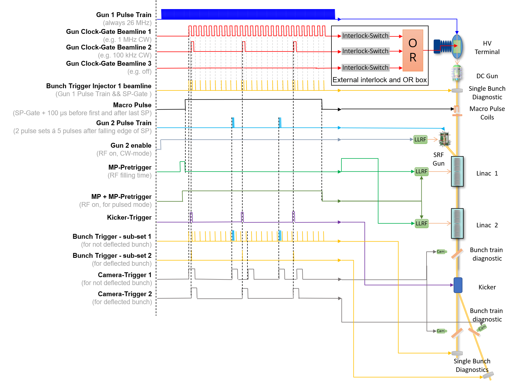
Figure 3 illustrates an example of a more complex operation mode that could be applied after the timing system upgrade. Here both injectors emit electron pulses into the ELBE accelerator. A kicker is used to split the beam of the first gun into two beamlines. For each beamline section, the corresponding gun emission triggers are generated and, later, the single bunch diagnostic triggers and the bunch train diagnostics.
The phase between the emission triggers can be set manually while the system automatically avoids gun emission triggers in the same RF bucket.
Output Jitter Performance
The output jitter was measured with two Micro Research Finland Universal I/O modules, one with UNIV-LVTTL and the second with a UNIV-LVPECL-DLY module, using a Rohde & Schwarz FSWP8 signal source analyser.
Measurements with the UNIV-TTL module show a jitter of 4.5 ps RMS in the interval of 1 Hz to 1 MHz, while measurements with the UNIV-LVPECL-DLY module show a jitter of 7.8 ps RMS in the interval of 1 Hz to 1 MHz.
Testing of the timing system
The system is currently under development on a few test benches. One is at our HQ, where we test the functionality while developing and supporting new functions. The second is at HZDR, where a team of engineers tests new features while still in development and thus provides a shorter feedback loop on implementation. The test bench at HZDR consists of two MicroTCA chassis equipped with two EVMs and four EVRs. In addition, HZDR set up a computer system to test the PCIe event receiver modules and analyse the generated patterns with three oscilloscopes.
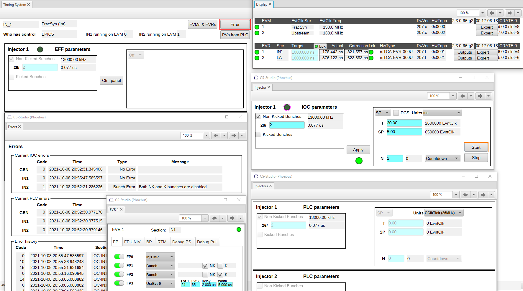
Over many iterations, we also developed a GUI for stand-alone operation in Control System Studio. The latter will serve as an expert GUI when ELBE commissions the system. The central part of the developed GUI is shown in Figure 4. It allows the users to set up the timing system parameters through EPICS variables. The users can — through the WinCC GUI — also check which parameters are configured and under which of them the timing hardware is currently operating.
The WinCC GUI also enables the configuration of individual outputs on event receiver modules by selecting predefined logic pulse patterns or with a specific pattern based on a separate event, delay and width. The status of the particular timing system hardware components is monitored and displayed in a dedicated GUI.
Summary
The ELBE centre for high power radiation sources operates an electron LINAC in either pulsed or continuous-wave mode to generate secondary radiation. The current timing system has been updated over the last two decades to enable new experiments, using parts that are now obsolete. HZDR has decided to modernise the system using the Micro Research Finland hardware platform.
The new timing system Cosylab is developing for the ELBE accelerator will be flexible and enable parallel operation of two-electron sources and future kickers to serve multiple end stations simultaneously.
First tests on-site with machine-wide integration at the ELBE accelerator are planned for the beginning of 2022, followed by a transition from the legacy timing system to the new timing generation and distribution.

