What is the space mission life cycle?
I’ll start by explaining what I mean by ‘Segment’. The latter encompasses all the elements of a space mission that are closely functionally related to each other and are grouped into a logical section to simplify the description of the complex interconnections of a mission. These are generally classified into:
- Ground Segment – consists of equipment and infrastructure for testing the satellite before it is launched and for executing mission operations;
- Launch Segment – consists of the launch vehicle and facilities at the launch site;
- Space Segment – consists of the satellite (or satellites, in case of a constellation) itself.
Now, to understand why Cosylab’s work is essential to guarantee the success of space missions, let’s get an overview of the typical steps in a space mission life cycle and what elements (belonging to one of the three above mentioned segments) are active in each step.
Space mission lifecycle
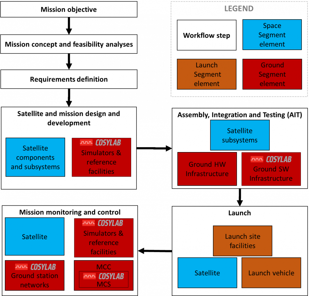
The figure below shows the steps in a typical space mission life cycle, along with the elements involved in each step. In it, I present the mapping of these elements to the Ground, Launch and Space segment. With our logo I have highlighted the elements on which Cosylab has worked on, is still working on, or expects to handle in the future, as it already possesses the contributing skills and experience.
In this blog, I provide a simplified overview, as every space mission has its particularities. In the following sections I have thus explained briefly the typical activities involved in each of the steps, together with a slightly detailed description of the steps in which Cosylab is involved.
1: Mission objective
A space mission is born out of the need for a product or service by private institutions or governmental agencies working in Space research. This need is formalised as a mission objective, taking into account high-level constraints. Some examples of primary objectives of famous missions follow.
- Gravity and steady-state Ocean Circulation Explorer (GOCE): to determine the Earth’s steady-state gravity field anomalies with an accuracy of 1e-5 m/s2 , and to assess geoid heights with accuracy between 1 to 2 cm, at length scales down to 100 km;
- Aelous: to provide accurate global measurements of winds from the surface up to 30 km;
- Gaia: to measure the positions and velocity of approximately one billion stars in our Galaxy, to determine their brightness, temperature, composition and motion through Space;
2: Mission concept and feasibility analyses
Once a mission objective is identified, engineers conduct mission analyses and identify constraints for the design of satellite subsystems and supporting ground infrastructure. A concurrent engineering approach is used to conduct trade-off studies, make decisions, and typically identify several stable mission architectures. After a mission concept is selected and the feasibility is confirmed, work starts on defining functional and operational requirements. During this phase, engineers’ decisions should account for required performance, implicit and explicit constraints, schedule, and risks.
3: Requirements definition
Functional requirements are flown down to the system level for both space and ground systems. These requirements are then decomposed and allocated to the subsystem level and interfaces between them. Even though this process is initiated using a top-down approach, reconciliation of system-level requirements with lower-level design development is commonplace. Engineers use system-level requirements to converge on the identification and definition of interfaces between all subsystems while using subsystem level requirements to identify specifications at the component level. This iterative process is very long and involves a multitude of stakeholders, and in most cases is even started even in the feasibility evaluation phase.
4: Satellite and mission design and development
Functional and operational mission requirements flown down to the satellite platform level are then taken down to the satellite subsystem level, and then from there to the components level to procure, design, and develop solutions for the satellite platform. Even during the design phase — and early during the Assembly, Integration and Testing phase — the software (SW) required to support the operation of the satellite subsystems should also be tested and verified. Engineers also investigate the characteristics of the selected orbit on the satellite design.
High-fidelity computer simulations typically simulate the satellite software and the space environment to detect and address possible failures and ensure that system-level requirements have been correctly brought down to the subsystem level. Defined interfaces must also be tested. These simulators and ‘reference facilities’ form part of the Ground Segment. Simulations for large satellites typically include sensor models (e.g., star trackers, sun sensors, earth sensors), actuators models (e.g., reaction wheels, thrusters, magnetic coils), and functional models of the power system management, telemetry control functions, the thermal management system, the fault detection and isolation system, and the propulsion system.
In Europe, reference facilities are present within ESA (European Space Agency) at ESTEC (European Space Research and Technology Center) which enable software-in-the-loop simulations, hardware-in-the-loop simulations, and provide several simulators for the environment, flight dynamics, onboard SW and data handling. Cosylab is in the process of analysing the critical design changes needed for integrating a next-generation control system in existing reference facilities hosted by ESA, making them adaptable to be able to host a range of missions.
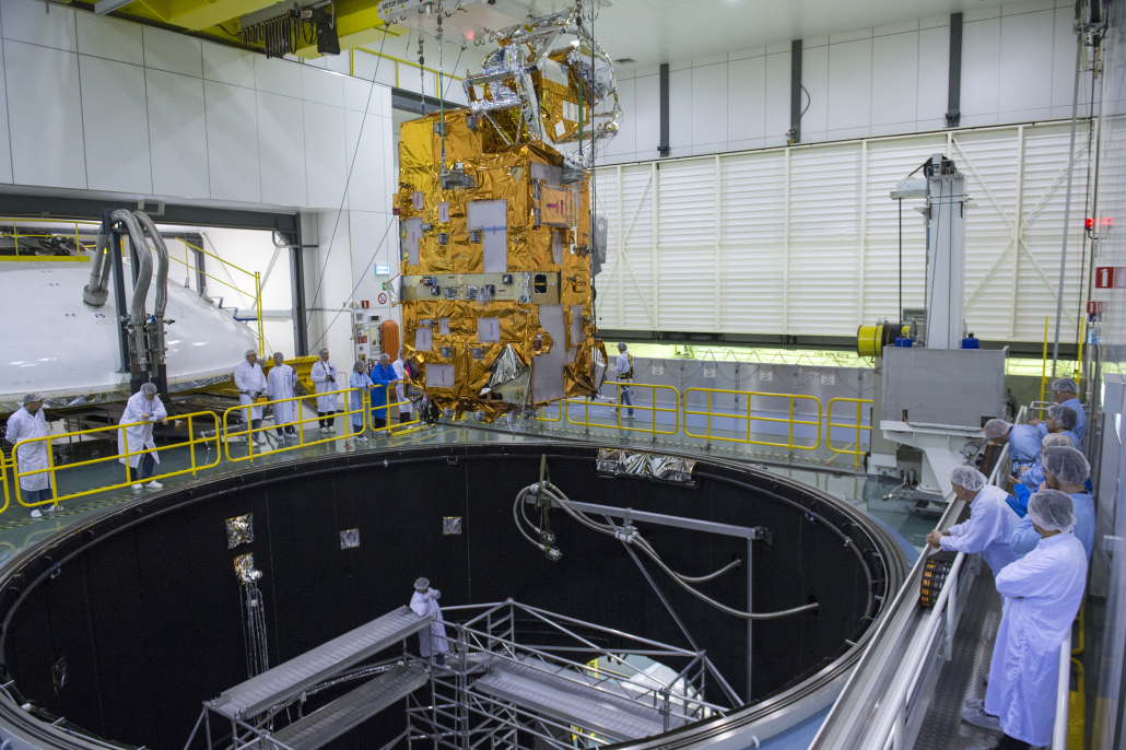
5: Assembly, Integration and Testing (AIT)
The subsystem components are then assembled, integrated into their higher-level assemblies, and thorough testing must ensure the subsystems can withstand the operating space environmental conditions and the extreme acoustic and mechanical environment during launch. Engineers can conduct testing at various integration levels, which is highly dependent on a multitude of programmatic and technical factors. The goal of this phase is to ‘qualify’ the systems for flight. For more details on How to Design Space Instrumentation, please refer to a previously published article by my Cosylab colleague Diego Casadei.
Many tests have to be accomplished in a predefined order to ensure that the satellite and its subsystems survive the launch and the harsh space environment. For activities in this phase, interfaces and equipment to ground infrastructure have to be provided, and it is the ground segment that takes care of this. Also provided by the ground segment are the necessary facilities required to carry out the tests, including (but not limited to) anechoic chambers, thermal-vacuum chambers and solar simulators, shakers and acoustic chambers.
Apart from mechanical tests, the supporting software — both Space and ground SW — is thoroughly tested and validated. Of course, for the whole ground segment to work correctly and be compliant with the mission requirements, the ground segment must also be the subject of systematic tests. The final goal before launch is that of operationally testing the entire ground segment.
In this phase, software plays an invaluable role. Traditionally, instrument and equipment developers had to develop whatever software was necessary to support them in their tasks to test the equipment/ subsystems while the Large System Integrators (“Primes”) were using their own software. In Europe, even ESA used different SW frameworks than the private entities. Thus, there was overlap in work in this phase and incompatible data exchange formats between various stakeholders due to a lack of a shared infrastructure. Also, agencies and integrators often use heterogeneous control systems during separate steps in the mission lifecycle. Thus, to minimise risks, reduce costs, and maximise the synergy between stakeholders and mission phases, ESA started the European Ground Systems Common Core (EGS-CC) initiative to develop a Ground Segment SW framework to support all the described use cases. Since a lot of the legacy software used is facing obsolescence, this framework is being developed with the modern SW development paradigms in mind. For more information on EGS-CC, please look at an article published by Cosylab colleague Miha Vitorovic (A Modern Infrastructure for the European Ground Control).
Cosylab has actively been participating in the development and testing of EGS-CC, with the following projects:
- EGS-CC Bus Adaptation: Starting in 2019, Cosylab worked with ESA on demonstrating the integration of various communication bus technologies (MIL-STD-1553, CAN/CANopen, SpaceWire) into the EGS-CC for different AIT use-cases. The project was successfully concluded in 2020.
- EGS-CC Consolidation: Cosylab, as part of a Consortium, since late 2020, has been carrying out EGS-CC system validation activities and quality assurance activities, and we successfully contributed to improving the sophistication, stability and maturity of EGS-CC, resulting in the kick-off of EGS-CC integration in its target environments.
Cosylab’s Space team is proud to be part of the EGS-CC consortium, even more so after EGS-CC was used successfully for the first time to monitor and control a spacecraft in Low Earth Orbit. We at Cosylab are already looking forward to participating in the further development and maintenance of EGS-CC!
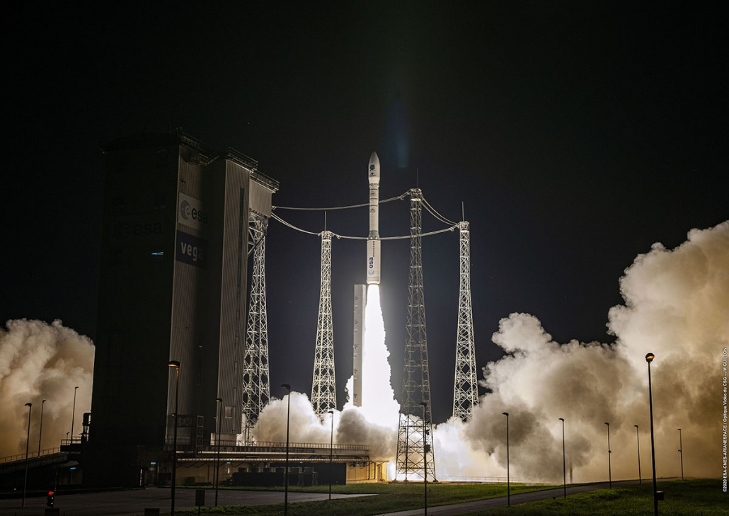
6: Launch
When the satellite is constructed and tested, it is shipped to the launch site, which consists of the launch vehicle itself and the supporting infrastructure at the launch site, of which there are 20 major ones in the world. After propellant loading and integrating the satellite in the launch vehicle, the launch vehicle is then transferred to the launch pad. The launch control centre coordinates the functioning of all required subsystems to ensure successful lift-off. Once the satellite is released from the launch vehicle at its target orbital destination, the mission enters the operations phase.
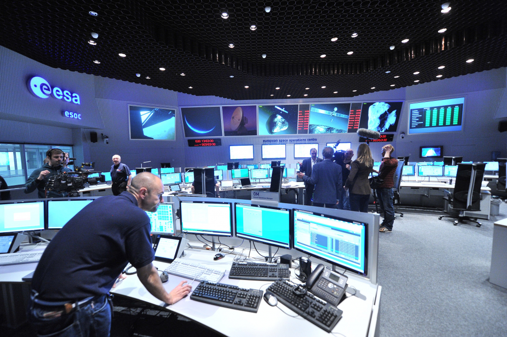
7: Operations
Once the satellite is in orbit, continuous support from the ground is required throughout the mission lifetime to enable mission success. Mission operations are where the interlinking of hardware, software and project staff is most visible. The operations are supported by a Mission Control Center (MCC). In MCC, all the action happens, and every time we see something on the news, it is this element of the Ground Segment we are seeing.
The Ground Segment communicates with the Space Segment through radio interfaces. Owing to the data volume, limited contact time between the satellite and the ground station, and desired low latency period between data reception and data relay to the ground station, radio interfaces between the satellite and ground are typically established through a ground station network.
With our competencies in device integration for distributed, time-critical systems, Cosylab is uniquely positioned to provide aerospace companies integration services for ground station networks.
The ground segment also gathers data from the spacecraft. It sends commands back to the spacecraft, with a Mission Control Center control acting as a sink for TeleMetry (TM) and as the source for TeleCommands (TC). Thus, the main functions of an MCC are:
Monitoring
The only way the status of the satellite in-orbit can be determined is by monitoring onboard data. This includes housekeeping data (temperatures, pressures, voltages, etc.) and data from scientific payloads. The On-Board Computer (OBC) gathers data from the satellite, packetised and then multiplexed into transfer frames for transmission to the ground. The MCC is responsible for anomaly detection in the received frames, calibration of telemetry parameters, limit checking, Space to ground time correlation and conversion of the raw satellite TM data to engineering values.
Commanding
The satellite operators are responsible for releasing commands to the ground station (or ground station network) for uplink to the satellite. The MCC also verifies all TC chain processes and offers data processing and archiving capabilities. On the uplink, the command and data handling system receives and decodes all commands and data received from the ground for both platform and payload operations. In some cases, the need may arise to redefine onboard algorithms or update the onboard software. Such critical changes are always validated with the aid of simulators before being uplinked to the satellite.
These functions are carried out through a so-called Mission Control System (MCS), which also includes a UI layer to make the life of the satellite operators easier. This layer provides to the satellite operator:
- Synoptic displays (combined display of graphic objects, texts and numeric values);
- Alarm handling and status checking;
- Interface to handle scripts sent to backend;
- User and role management capabilities;
- Session management capabilities;
- Representation of data in graphical/ tabular format;
- Ability to work in fast forward/ retrieval mode.
The MCS-element is exactly what we are involved within the scope of the New Generation User Interface for Operational Monitoring and Control Applications (NeGUIOMCA) project. Within the latter, Cosylab is working closely with ESA/ESOC to upgrade their existing control system User Interface (UI) to be compatible with the next-generation control system, EGS-CC. Our work involves work on all layers of the UI: the presentation, services and communication layers. This project kicked off in 2020 and is currently in full swing.
In the last few years, Cosylab has invested a lot of effort in analysing the requirements for an innovative and comprehensively rethought MCS, and its design that ground-breaking (pun intended) space mission operators demand.
Conclusion
With this blog, I wanted to give the reader unfamiliar with the Space domain a very high-level overview of the steps in a typical space mission lifecycle and where Cosylab fits in.
Cosylab is well on its way to dealing with increasingly demanding space projects and is on the cusp of entering the world of On-Board Software. We believe that humankind’s future is in Space and the direction of Stars, so we feel compelled to use our experience and know-how to support Space efforts.
About the author

Subscribe to our newsletter
What kind of content are you interested in?