A Novel Approach to Triggering and Beam Synchronous Data Acquisition
Introduction
A solution was needed for triggering sensor readout electronics and transferring the measurement data. At the same time slow control and status data had to be transferred over the same full-duplex optical connection. A unique pulse ID had to be send to the readout electronics with each trigger pulse to enable deterministic tagging of the data for the purpose of later analysis. A new protocol had to be specified, since none of the available protocols fulfilled all requirements. The first implementation was successfully used as a bidirectional link between two nodes and showed to also be useful in other systems.
System Overview
Deterministic Event Latency Fiber Interface (DELFI) link is used in SwissFEL between Frontend Electronics crate and controls crate. The first one is placed in proximity of the sensors and the latter one is mounted in a 19” rack on a distant location. The Frontend Electronics crate consist of a Communication Board (Comm. Board) which interfaces an analog to digital converter (ADC) and Analog Frontend, ie. electronics, responsible for conditioning the analog signals before they enter ADC. Controls Hardware is based on a VME form factor single board computer IFC1210 which features Virtex-6 FPGA and a P2020 processor [6]. A 4 port SFP FMC module is connected to IFC1210 and enables optical connections to the SwissFEL Event Timing System, and to DELFI devices. Configuration parameters, status and measurement data are exposed over EPICS Channel Access (CA) protocol, measurement data is also streamed to the (Beam Synchronous) Data Acquisition Dispatching Layer (BS DAQ System) [1][3]. DELFI Link enables triggering, transmission of the measurement data and transmission of the control and status parameters simultaneously.
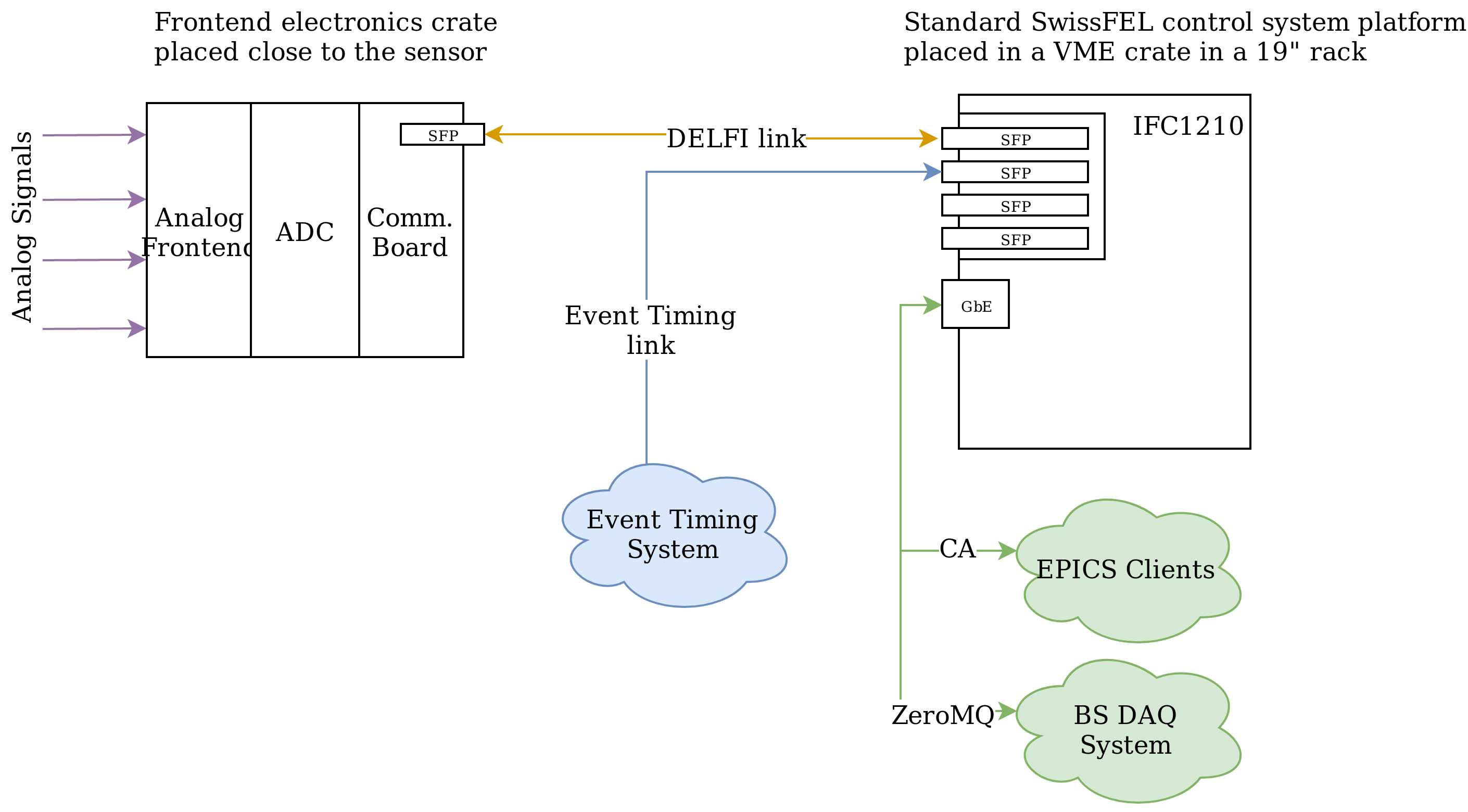
Figure 1: System overview
DELFI Protocol
The DELFI protocol is a lightweight system level protocol that allows deterministic event transmission as well as high-speed and low latency data transportation. The DELFI Core-Layer makes no assumptions about the data itself. An additional Data-Definition-Layer allows a combination of memory-mapped and streaming interfaces. The optional Routing Layer permits routing of data packages in various system topologies. DELFI is very scalable and many parameters like maximum event data size or link data rate may be adjusted on a per system or even subsystem base.
Requirements
DELFI protocol aims to fulfill the following requirements:
- Data and event transfer
- Events have highest priority and fixed deterministic latency
- Data packets for single access and burst (block) transfer
- Data streaming to different channels (ports)
- Low data transfer latency, low protocol overhead
- Easy to implement, Low FPGA resource usage
- Link data-rate can be selected per system or subsystem
- Open source, license free and manufacturer independent
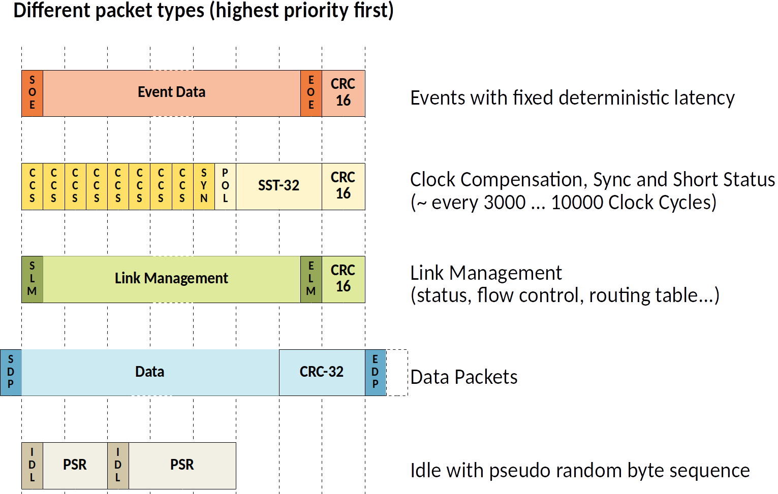
Packet Types
DELFI protocol defines packet types with different priorities. The DELFI Core guarantees that the highest priority packet, i.e Event Packet is always transmitted with a deterministic latency. Other packets with lower priorities are responsible for clock compensation, link management and data transfer. Different types of data packets exist which support different read and write operation e.g. single register read, single register write, block read, block write. If the link is idling it is transfering a special idle sequence. Protocol uses 8b/10b encoding [4]. Special K characters are used as start and termination characters or serve as other signals.
Figure 2: Different packet types, highest priority first. The protocol guarantees that the Event Data packet is always transmitted with deterministic latency.
Control System integration
Standard Control System Computational platform for SwissFEL is a single board computer (SBC) IFC1210 [6]. It features a Virtex 6 FPGA and processor (POWER PC P2020). For the communication between them a special design kit is provided by the hardware vendor. It includes a design kit for the FPGA (TOSCA II [7]) and a corresponding EPICS driver [8] for the processor. A two part application, consisting of an FPGA gateware and EPICS input/output controller (IOC), was written to support communication over DELFI link, integration to other sub-systems of the SwissFEL environment and and graphical user interface (GUI).
The application differentiates between two types of data transfer over DELFI: Slow, control and status parameters, and fast, measurement data. Measurement data is copied to shared memory while control and status parameters are exposed to the processor over TOSCA-II directly.
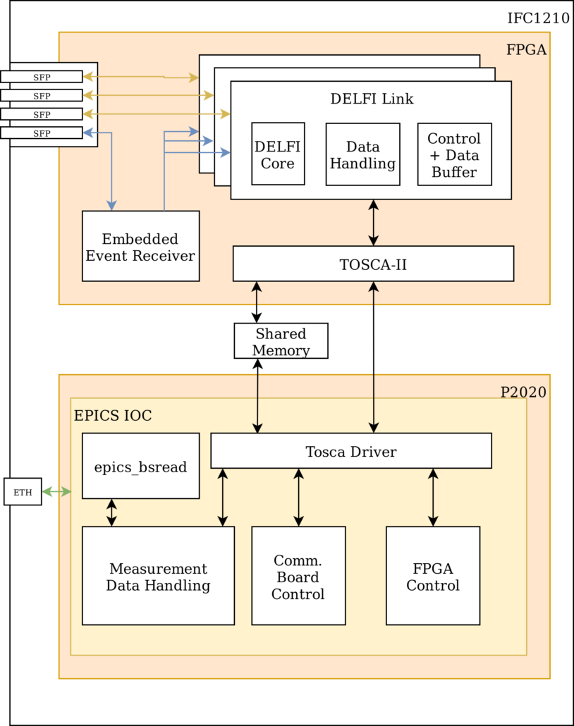
Figure 3: FPGA and EPICS IOC block diagram
FPGA
Embedded Event Receiver (EVR) [2], [5] FPGA core was used to the interface the Event Timing System directly on the FPGA directly.
The DELFI Core FPGA components provide 4 interfaces: Event Interface, Data Interface, Short Status and Management Interface, of which the latter one is not used in this application. The Event Interface is only used in direction master (IFC1210) to slave (Comm. Board) to trigger the data acquisition and deliver the Pulse ID to the Comm. Board. The TX Data Handler block sends (slow) configuration write and status read requests to the slave. The responses from these requests are captured by the RX Data Handler block which differentiates them from the (fast) measurement data and routes them to a different location. Slow data ends up in an RX buffer, which is directly exposed through TOSCA II to the processor, and fast data is routed through several stages to the shared memory. Beforehand the correct reception in the Packet FIFO is checked. All incomplete or erroneous packets are dropped in the Packet FIFO.
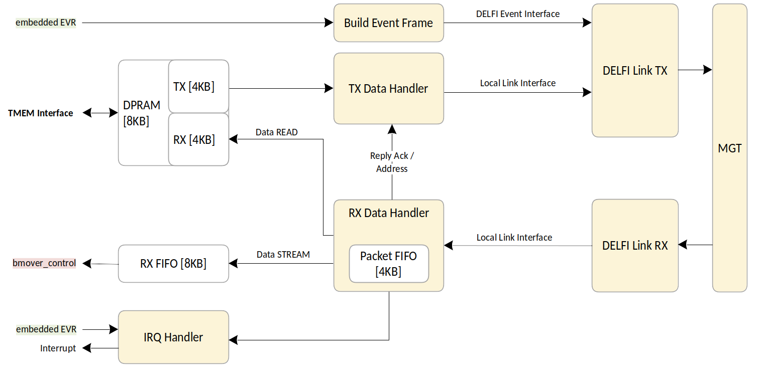
Figure 4: TX and RX data handling blocks on the FPGA
EPICS IOC
EPICS IOC exposes all configuration parameters, statuses and measurement data as EPICS Process Variables (PVs). It consists of three main parts: FPGA Control, exposes application specific configuration particular to the FPGA, Comm. Board control exposes the parameters of the Comm. Board (slow data), and the Measurement Data Handling exposes the measurement data (fast data). Additionally the Measurement Data Handling also sends the measurement data to the Beam Synchronous Data Acquisition Dispatching Layer by using already prepared EPICS driver for this purpose (epics_bsread).
Measurement data handling takes the following course for every pulse of the machine (Figure 5): Unique Pulse ID is delivered from the Timing System to the FPGA for each pulse. The Pulse ID is received by the Embedded Event Receiver on the IFC1210 FPGA and transmitted as DELFI Event Data to the Comm. Board. The Comm. Board acquires data and adds the Pulse ID in the header of the data frame when sending it over DELFI link back to the FPGA. This way the data is reliably tagged with correct pulse ID. EPICS IOC exposes all the data over Channel Access (CA) protocol and also streams the data to the Beam Synchronous Data Acquisition Dispatching Layer.
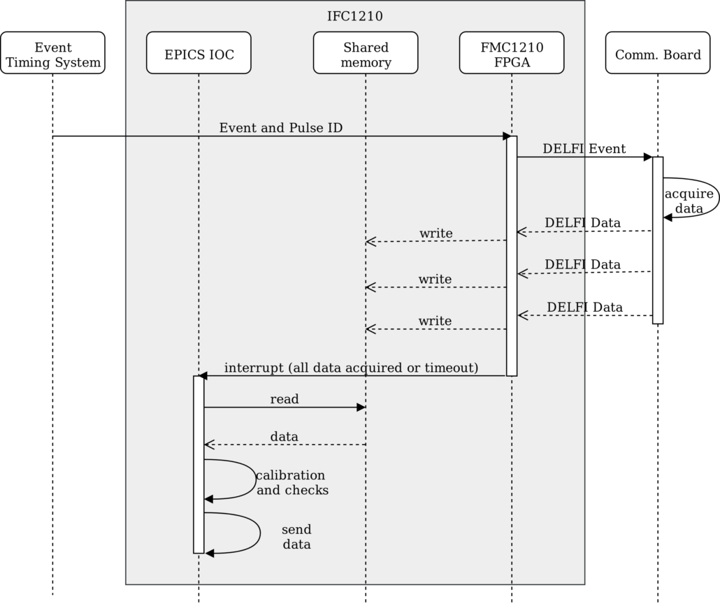
Figure 5: Sequence diagram of one machine pulse
User Interface
A graphical user interface was developed in CaQtDm [9] which provides a full control over all parts of the application from configuring the analog frontends through changing data acquisition parameters on the Comm. Board to configuring the embedded EVR.
Challenges
The application was first designed to handle 15 DELFI links and one Event Timing Link on one IFC1210. At this point it was not yet clear whether the calibration procedure will run on the IFC1210 or will it be done off-line. Once the calibration was implemented on the IFC1210 it turned out that the processor can not process that amount of measurement data in the available time. The number of links per IFC1210 was reduced. Currently all installations are using only one DELFI link per IFC1210.
The majority of the EPICS IOC was written in EPICS database files which became difficult to maintain. In some cases it was also limiting the functionality. Parts of the the application had to be rewritten later to C.
It was observed that the data delivered to the Beam Synchronous Data Acquisition Dispatching Layer was not always consistent. Tests are being developed to confirm the inconsistency and at the same time parts of the application are being improved to address this issue.
Conclusion
DELFI protocol was developed to allow deterministic triggering and data acquisition over the same full duplex serial interface. It was integrated into the SwissFEL environment and proven to work in practice. It is already planned to be used in other facilities at Paul Scherrer Institute.
REFERENCES
[1] C.Milne, et al.,“SwissFEL: The Swiss X-Ray Free-Electron Laser”, inApplied Sciences (Switzerland), vol. 7, no. 7, article 720, Jun. 2018
[2] Kalantari and R. Biffiger, “SwissFEL Timing System: First Operational Experience”, inProc. 16th Int. Conf. on Accelerator and Large Experimental Control Systems (ICALEPCS’17), Barcelona, Spain, Oct. 2017, pp. 232-237. doi:10.18429/JACoW-ICALEPCS2017-TUCPL04
[3] G. Ebner et al., “SwissFEL – Beam Synchronous Data Acquisition – The First Year”, inProc. 16th Int. Conf. on Accelerator and Large Experimental Control Systems (ICALEPCS’17), Barcelona, Spain, Oct. 2017, pp. 276-279. doi:10.18429/JACoW-ICALEPCS2017-TUCPA06
[4] A. Franaszek and A. X. Widmer,“A DC-Balanced, Partitioned-Block, 8B/10B Transmission Code” inIBM Journal of research and development, vol. 27, no. 5.,1983
[5] Kalantari, R. Biffiger, S. Skube, T. Slejko, T. Šuštar, “SwissFEL Event Timing System”, poster atAnnual meeting of the Swiss Physical Society, Lausanne, Switzerland, 2018.
[6] IOxOS Technologies AS, “IFC_1210 – Intelligent FPGA Controller P2020 VME64x Single Board Computer”, Data Sheet, 2011
[7] IOxOS Technologies AS, “TOSCA II Xilinx Virtex-6T FPGA Design Kit”, Data Sheet, 2010
[8] IOxOS Technologies AS, “EPICS Driver for TOSCA II Infrastructure IFC_1210”, Data Sheet, 2013
[9] http://epics.web.psi.ch/software/caqtdm/
This article was originally published at IPAC19 in Melbourne, Australia.
Content from this work may be used under the terms of the CC BY 3.0 licence ( © 2019). Any distribution of this work must maintain attribution to the author(s), title of the work, publisher, and DOI.
10th Int. Particle Accelerator Conf., IPAC2019, Melbourne, Australia.
JACoW Publishing, ISBN: 978–3–95450–208–0
DOI: 10.18429/JACoW-IPAC2019-THPTS054